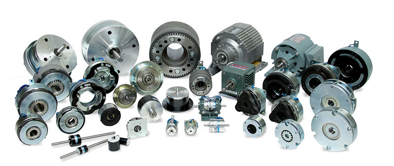
Industrial Clutches and Brakes
for Robotics, Processing and Automation Equipment
Electomagnetic Clutch
Electromagnetic Clutches and Brakes
Ogura's industrial electromagnetic clutches, electromagnetic brakes and clutch brakes are used in many types of high speed, high cycle rate and long life machines including printers, packaging machines, food processing equipment, industrial mixers, and cash counting machines.
Our magnetic particle, hysteresis slip clutches and magnetic particle, hysteresis slip brakes are used in many tension control systems to regulate the wind and unwind of fabric or carbon fiber or other materials during processing. Also called particle clutches or particle brakes, they are used in new digital high resolution sign and photograph printers for professionals. Many designs are interchangeable with Warner Electric, DynCorp, KEB, Electroid, Lenze, Deltran, Intorq and Matrix.
Our spring applied brakes, power off brakes, or spring set brakes (formally known as failsafe brakes) are used in mobile, medical and robotic applications as well as used in radio telescopes. Also called servo motor brakes, they are also used to control electric wind generators, turbines and amusement rides from over speed conditions.
Our industrial electric brakes are used in rail road crossing gates and parking lot/toll gates. These devices are also used in mailing machines, mail sorters and semiconductor processing applications. Electric tooth clutches and electric multiple disc clutches are used where high torque and small size are required. Our customers include machine tool manufacturers, CNC machines, lathes, milling machines and others. They are used by manufacturers of AC and DC electric motors including brake motors, brushless DC motors and servo motors.
Applications for Ogura high reliability brakes include overhead doors, cranes, marine, construction equipment and brakes for super quiet use in stage and theater equipment. Manual release levers or emergency release mechanisms can be available on many of these products if needed. Robust products such as x-ray machine brakes and conveyor clutches are also made by Ogura. Among our highest volume production applications, our copy machine clutches and PM hysteresis clutches are used by all leading copy and printer manufacturers for their low cost, high torque, long life and zero maintenance.
Types of Electromagnetic Clutches
 Electromagnetic Tooth Clutch
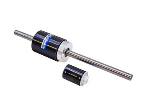 Permanent Magnetic Hysteresis Clutch
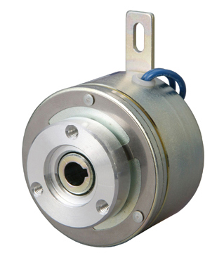 Electromagnetic Clutch
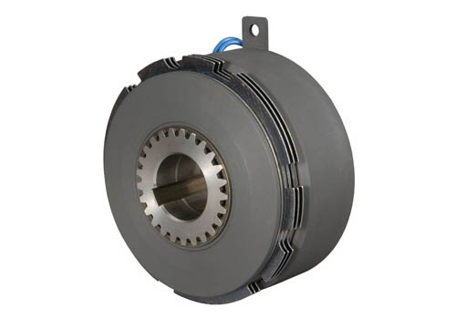 Electromagnetic Multiple Disc Clutch
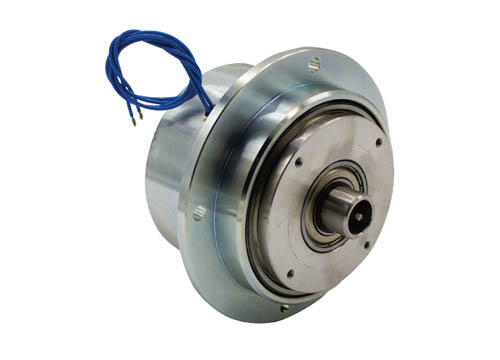 Magnetic Particle Clutch
Types of Electromagnetic Brakes
 Multiple Disc Brakes
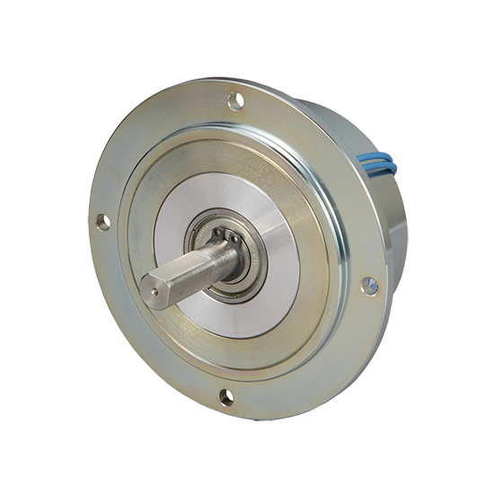 Magnetic Particle Brakes
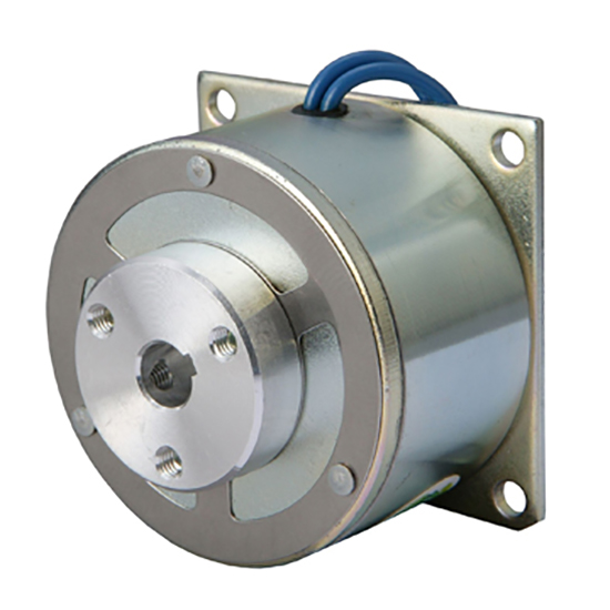 Electromagnetic Brakes
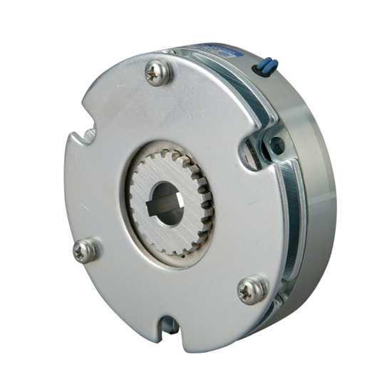 Electromagnetic Power Off Brake
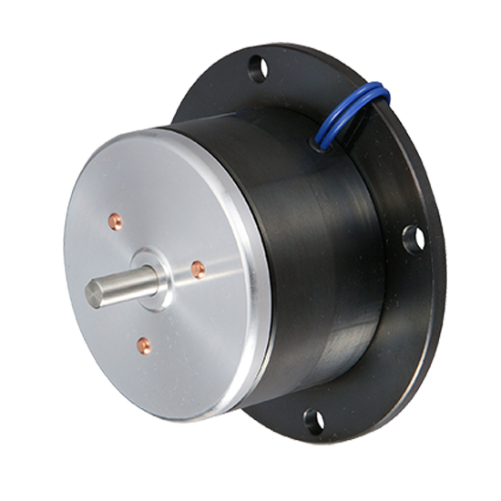 Permanent Magnetic Hysteresis Brakes
- Electromagnetic Clutches
- Electromagnetic Brakes
- Electromagnetic Spring Applied Brakes
- Electromagnetic Power Off Permanent Magnet Brakes
- Multiple Disk Electromagnetic Clutches
- Multiple Disk Electromagnetic Brakes
- Electromagnetic Tooth Clutches
- Electromagnetic Particle Clutches
- Electromagnetic Particle Brakes
- Hysteresis Permanent Magnet Clutch or Brake
- Powered Hysteresis Clutches
- Powered Hysteresis Brakes
How Industrial Clutches and Brakes Work
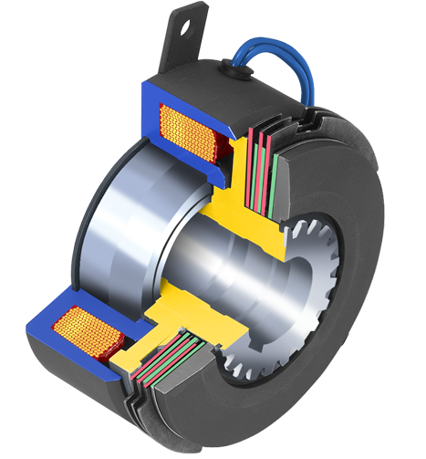
Electromagnetic Clutches
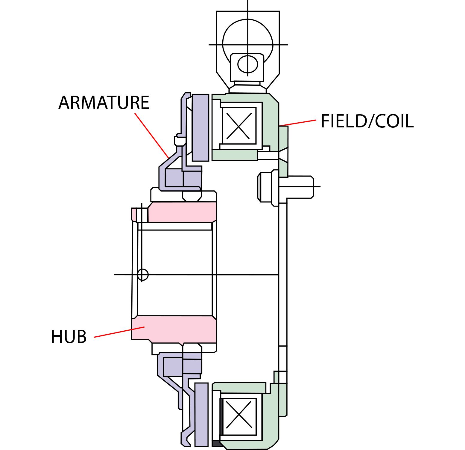
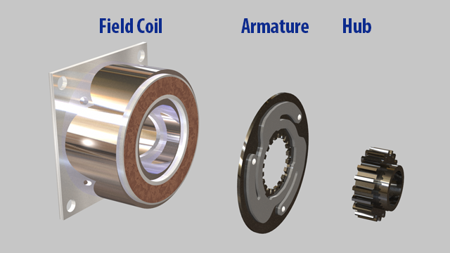
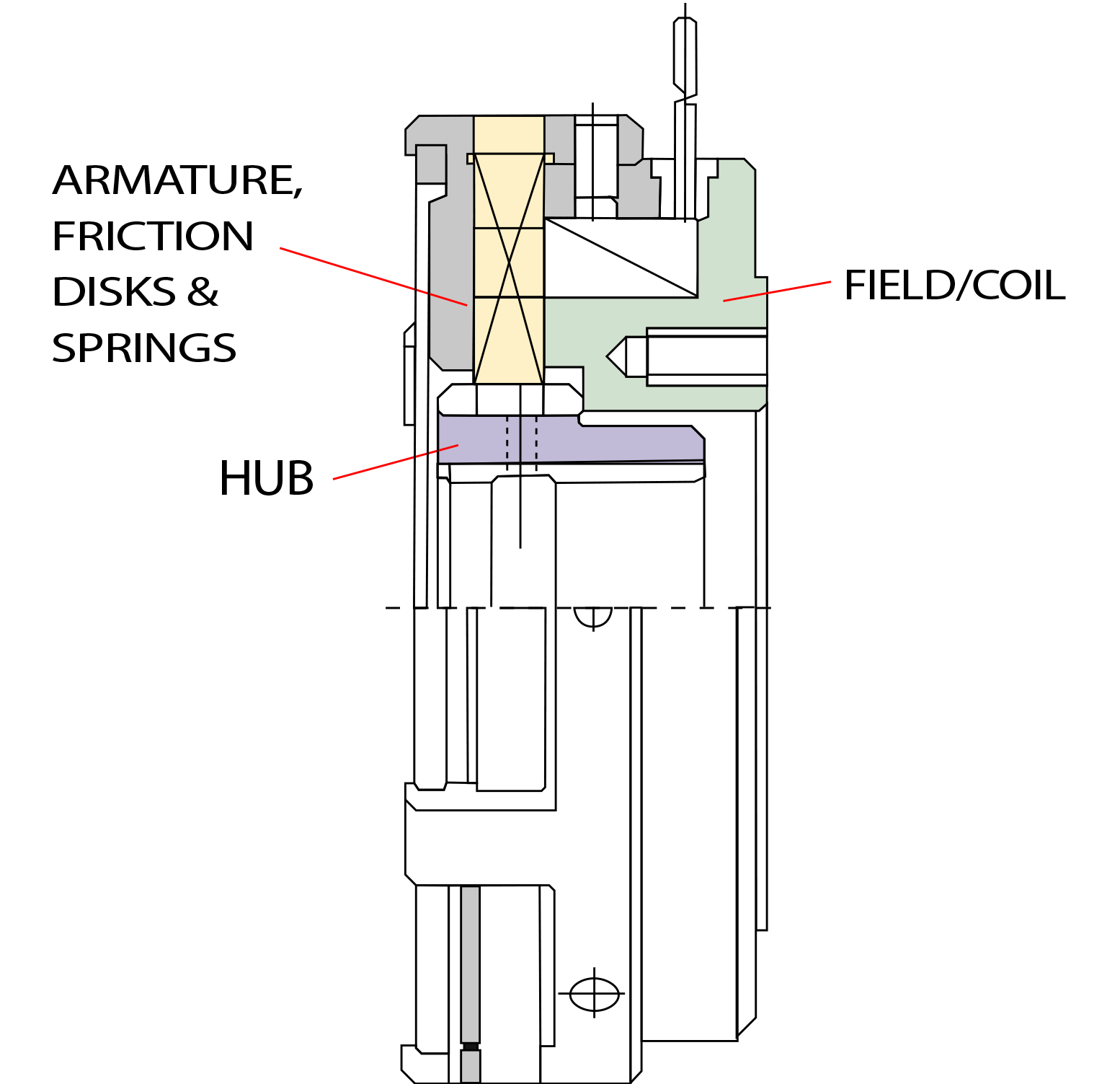
Electromagnetic clutches are comprised of a coil, field and a hub. Activating the unit’s electric circuit energizes the coil. The current running through the coil generates a magnetic field. When magnetic flux overcomes the air gap between the armature and field, magnetic attraction pulls the armature towards the rotor and makes contact.
Magnetic and friction forces accelerate the armature and hub to match rotor speed. For the first 0.02 to 1.0 seconds, the rotor and armature slip past each other. Then the input and output speeds will match. The matching of speeds is sometimes called 100% lockup.
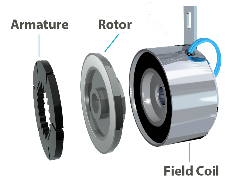
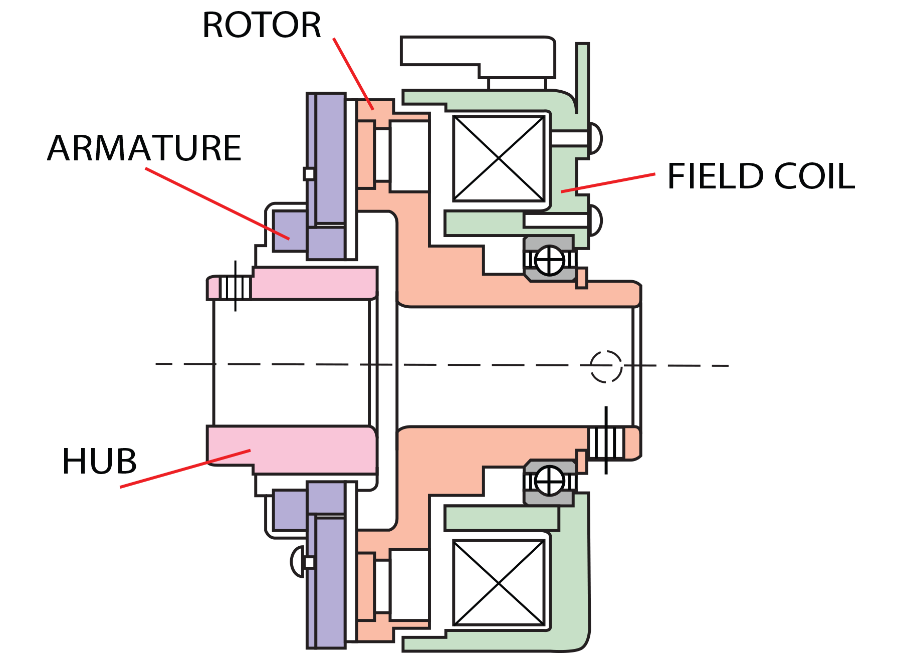
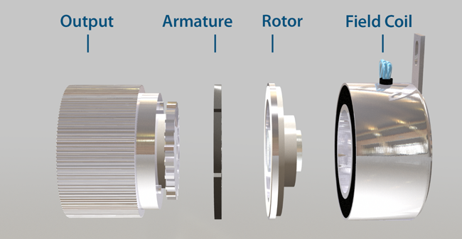
Electromagnetic Clutch
Engagement: Electromagnetic clutches operate via an electric actuation, but transmit torque mechanically. When the clutch is required to actuate, voltage/current is applied to the clutch coil. The coil becomes an electromagnet and produces magnetic lines of flux. This flux is then transferred through the small air gap between the field and the rotor. The rotor portion of the clutch becomes magnetized and sets up a magnetic loop that attracts the armature. The armature is pulled against the rotor and a frictional force is applied at contact. Within a relatively short time the load is accelerated to match the speed of the rotor, thereby engaging the armature and the output hub of the clutch. In most instances, the rotor is constantly rotating with the input all the time.
Disengagement: When current/voltage is removed from the clutch, the armature is free to turn with the shaft. In most designs, springs hold the armature away from the rotor surface when power is released, creating a small air gap.
Cycling: Cycling is achieved by turning the voltage/current to the coil on and off. Slippage should occur only during acceleration. When the clutch is fully engaged, there is no relative slip (if the clutch is sized properly). Torque transfer is 100% efficient.
Electromagnetic Clutches - how they work video
Electromagnetic Brakes
These brakes use a single plate friction surface to engage the input and output members of the brake. This style of brake is used in applications ranging from copy machines to conveyor drives. They are the most common type of electromechanical brakes. Other applications for these brakes could include packaging machinery, printing machinery, food processing machinery and factory automation.
Zero backlash armature available on some units: The armature is mounted to the hub by a special leaf spring to provide minimal backlash and no armature rattle.
Automatic air gap available on some units: Clutch air gap automatically adjusts as the brake wears, allowing for a consistent air gap that maintains a consistent time to stop.
Fast Response: The single friction plate design allows for a very fast response in high cycle applications.
Smooth, quiet operation: Whether automatic air gap or zero backlash is chosen, brake armatures engage smoothly, eliminating chattering noise, helping in sustaining quieter operation.
Electromagnetic Brakes - how they work video
Engagement: Electromagnetic brakes operate via an electric actuation, but transmit torque mechanically. When voltage/current is applied, the coil is energized creating a magnetic field. This turns the coil into an electromagnet that develops magnetic lines of flux. The magnetic flux attracts the armature to the face of the brake. The armature and hub are normally mounted on the shaft (customer supplied) that is rotating. Since the brake coil is mounted solidly, the brake armature, hub and shaft come to a stop in a short amount of time.
Disengagement: When current/voltage is removed from the brake, the armature is free to turn with the shaft. In most designs, springs hold the armature away from the brake surface when power is released, creating a small air gap.
Cycling: Cycling is achieved by turning the voltage/current to the coil on and off. Slippage should occur only during deceleration. When the brake is engaged, there should be no slippage once the brake comes to a full stop.
Electromagnetic Spring Applied Brakes
Spring applied brakes stop or hold a load when electrical power is either accidentally lost or intentionally disconnected. In the past, some companies have referred to these as "fail safe" brakes. These brakes are typically used on or near an electric motor. Typical applications include robotics, holding brakes for Z axis ball screws and holding brakes for servo motors. Many custom designs are available and can be made for use with different motor applications.
Small profile: High torque in a small space makes for a very compact design brake.
Zero backlash option: Some designs contain a zero backlash hub that can be critical in registration applications.
Fast response time: In most units, a series of coil springs are used so pressure plate travel is minimized.
Multiple voltages available: Depending upon the size, 24, 45 or 90 volts are available; however, voltages can be modified to meet your special requirements.
Spring Applied Brakes - how they work video
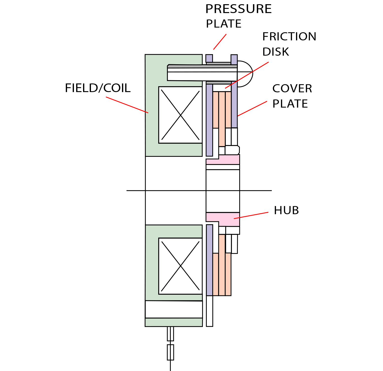
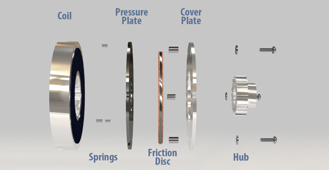
Engagement: When no current/voltage is applied to the brake, a series of springs push against the pressure plate, squeezing the friction disk between the inner pressure plate and the outer cover plate. This frictional clamping force is transferred to the hub, which is mounted to a shaft (customer supplied).
The power off brake is considered engaged when no power is applied to it. It is typically required to hold or stop a load in the event of a loss of power, when power is not available to run a machine.
Disengagement: When the brake is required to release, voltage/current is applied to the coil creating a magnetic field. This magnetic field pulls in the pressure plate pulling against the springs, creating an air gap between the pressure plate and the friction disk, allowing it to turn freely with the shaft.
Power Off Permanent Magnet Brakes
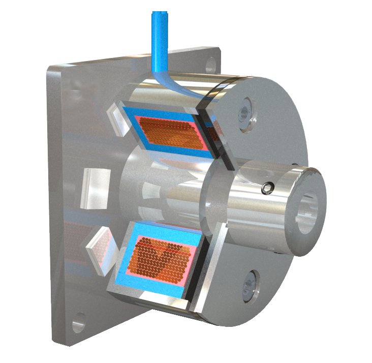
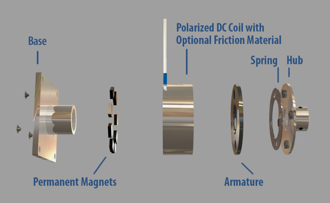
Electromagnetic, direct current permanent magnet brakes operate similar to spring applied brakes but have some unique properties. Electromagnetic permanent magnet brakes are designed to stop and hold a rotating shaft or to simply hold the shaft in place. Their function is opposite from a traditional electromagnetic brake. When no electric power is going to the brake, the brake is considered engaged and holding. The two main reasons for using these brakes are safety and accuracy.
Small profile: Smaller diameter and are lighter in weight than spring applied brakes.
Zero backlash: Critical in medical and other high precision applications.
Fast response time: Brake coils are normally 90 or 24 volts DC. To reduce engagement time, a diode can be used to help collapse the magnetic field faster.
Variable torque: Permanent magnet brake torque can be controlled.
Power Off Permanent Magnet Brakes - How they work video
Engagement: Brakes are engaged magnetically and disengaged electrically. Powerful rare-earth magnets on the base of the brake create magnetic flux. This flux is free to travel through the coil shell creating a magnetic attraction between the coil shell and the armature.
Disengagement: When voltage or current is applied to the brake, the coil becomes an electromagnet. This produces magnetic lines of flux, which opposes and negates the force created by the permanent magnets. The spring pulls the armature away from the coil shell creating an airgap, so the hub and whatever is attached to the hub is free to rotate.
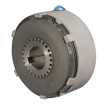
Multiple Disk Electromagnetic Clutches
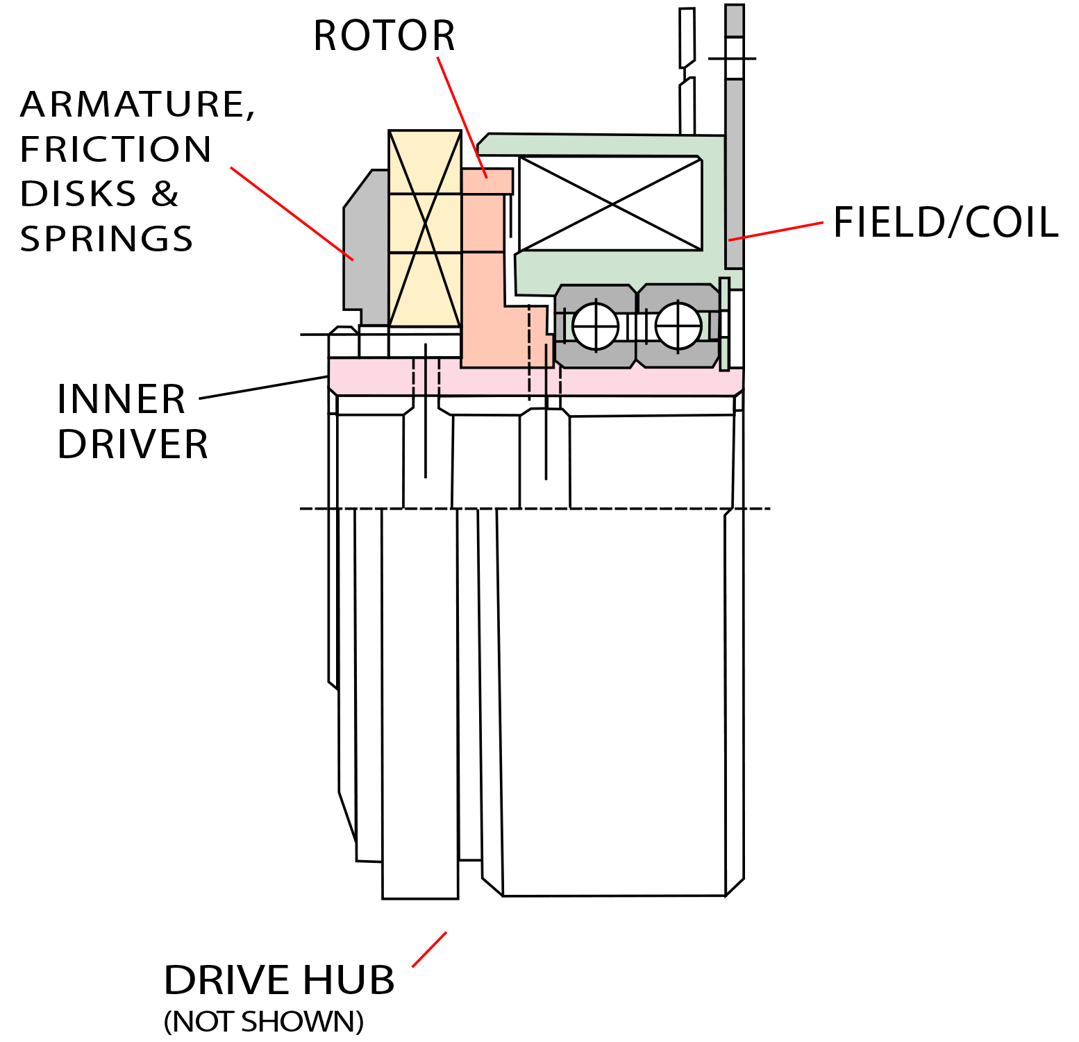
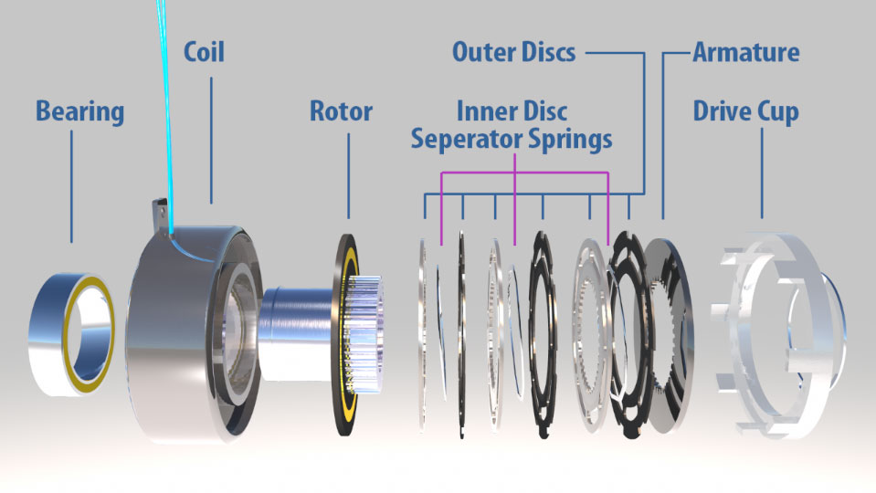
Multiple disk clutches are used to deliver extremely high torque in minimal dimensional requirements. These clutches can be used either wet or dry, which makes them ideal to run in multiple speed gear box applications. Machine tool applications top the list where these clutches are used.
High torque/compact design: The multiplication of surface area in a multiple disk clutch allows for one of the smallest torque to size ratios available.
Wet or dry application: Clutches can be used in an oil/gear box environment (wet), or as a stand alone clutch (dry).
Fast Response (wet): For fast response special channels are cut in the friction disks to allow the oil to flow faster.
High heat dissipation (wet): In an oil environment, the oil is used to take heat away from the friction disks for better heat dissipation.
Multiple Disc Clutches - How they work video
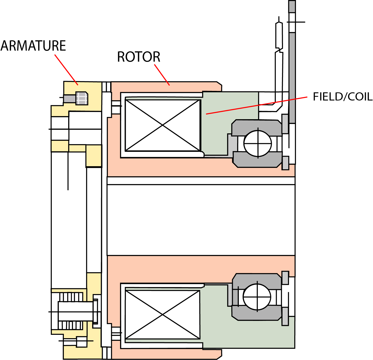
Engagement: Electromagnetic clutches operate via an electric actuation, but transmit torque mechanically. When voltage/current is applied to the clutch coil, the coil becomes an electromagnet and produces magnetic lines of flux. This flux is then transferred through the small air gap between the field and the rotor. The rotor portion of the clutch becomes magnetized and sets up a magnetic loop, which attracts both the armature and the friction disks. The attraction of the armature compresses or squeezes the friction disks, transferring the torque from the inner driver to the outer disks. (In order for the unit to be used as a clutch, a drive hub is required. This hub would be attached to a pulley, sprocket or coupling.) Within a relatively short time, the load is accelerated to match the speed of the rotor, thereby engaging the armature and the output portion of the clutch.
Disengagement: When current/voltage is removed from the clutch, the armature is free to turn with the shaft. Springs hold the armature away from the rotor surface when power is released, creating minimal drag.
Cycling: Cycling is achieved by turning the voltage/current to the coil on and off. Slippage should occur only during acceleration. When the clutch is fully engaged, there is no relative slip (if the clutch is sized properly). Torque transfer is 100% efficient.
Multiple Disk Electromagnetic Brakes
Multiple disk brakes are used to deliver extremely high torque in minimal dimensional requirements. These brakes can be used either wet or dry, which makes them ideal to run in multiple speed gear box applications. Machine tool applications top the list where these brakes are used.
High torque/compact design: The multiplication of surface area in a multiple disk brake allows for one of the smallest torque to size ratios available.
Wet or dry application: Brakes can be used in an oil/gear box environment (wet), or as a stand alone clutch (dry).
Fast Response (wet): For fast response special channels are cut in the friction disks to allow the oil to flow faster.
High heat dissipation (wet): In an oil environment, the oil is used to take heat away from the friction disks for better heat dissipation.
Engagement: Electromechanical brakes operate via an electric actuation, but transmit torque mechanically. When voltage/current is applied to the coil, it creates a magnetic field. This turns the coil into an electromagnet, which develops magnetic lines of flux. The magnetic flux attracts the armature to the face of the brake. As it does so, it squeezes the inner and outer friction disks together. The armature and hub are normally mounted on the shaft (customer supplied) that is rotating. Since the brake coil is mounted solidly, the brake armature, hub and shaft come to a stop in a short amount of time.
Disengagement: When current/voltage is removed from the brake, the armature is free to turn with the shaft. Springs hold the armature away from the brake surface when power is released, creating a minimal drag.
Cycling: Cycling is achieved by turning the voltage/current to the coil on and off. Slippage should occur only during deceleration. When the brake is engaged, there should be no slippage once the brake comes to a full stop.
Electromagnetic Tooth Clutches
Electromagnetic tooth clutches offer the greatest torque in the smallest package size. Because the clutches can be made for zero backlash, they are very good for printing applications where a number of stations need to be timed together, but occasionally are required to disengage. The units can be made with a single position option to allow precise timing. Tooth clutches are also ideal for applications that are engaging at very low rpm. Gear box and machine tool applications are also ideal for tooth clutches.
High torque/compact design: Tooth clutches provide the highest torque per size of any electromagnetic clutch style.
Single position style available: Optional tooth clutches can offer single position for precise registration applications.
No slip: Torque is driven via tooth, so slippage is non-existent when clutch is engaged.
Zero backlash: As an option, tooth profile can be made to produce zero backlash when clutch is engaged.
Zero drag torque: There is no drag torque in the disengaged position because there is no tooth contact.
Wet/dry applications: Tooth clutches can be used in either wet (oil/gear box) or dry applications.
Electromagnetic Tooth Clutches - How they work video
Engagement: Electromechanical tooth clutches operate via an electric actuation, but transmit torque mechanically. When voltage/current is applied to the clutch coil, the coil becomes an electromagnet and produces magnetic lines of flux. This flux is then transferred through the small air gap between the field and the rotor. The rotor portion of the clutch becomes magnetized and sets up a magnetic loop, which attracts the armature teeth to the rotor teeth. In most instances, the rotor is constantly rotating with the input (drive). As soon as the clutch armature and rotor are engaged, lock up is 100%. (Because of this instantaneous engagement, tooth clutches cannot be engaged above 50 rpm.)
Disengagement: When current/voltage is removed from the clutch, the armature is free to turn with the shaft. Springs hold the armature away from the rotor surface when power is released, creating a small air gap.
Cycling: Cycling is achieved by turning the voltage/current to the coil on and off. When the clutch is running, there is no relative slip. Torque transfer is 100% efficient.
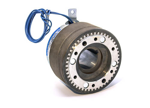
Electromagnetic Particle Clutches
Magnetic particle clutches are unique in their design from other electromagnetic clutches because of the wide operating torque range available. Like an electromagnetic clutch, torque to voltage is almost linear; however, in a magnetic particle clutch, torque can be controlled very accurately (within the operating rpm range of the unit). This makes these units ideally suited for tension control applications, such as wire winding, foil and film tension control and tape tension control. Because of their fast response, they can also be used in high cycle applications, such as magnetic card readers, sorting machines and labeling equipment.
Fast response and accurate control: Voltage to torque is almost linear, so engagement is extremely fast, and controllability of magnetic particle units is very accurate.
Stable torque: Torque is independent of speed, but is proportional to the voltage/current applied to the field, allowing stable torque throughout the units operating rpm range.
Long life: Torque is driven via tooth, so slippage is non-existent when clutch is engaged.
Excellent slip capacity: Because of the units' excellent heat dissipation, and because of their construction, they can operate in a constant slip mode (within max. allowable wattage), which makes them ideal for tension controlling applications.
Electromagnetic Particle Clutches - How they work video
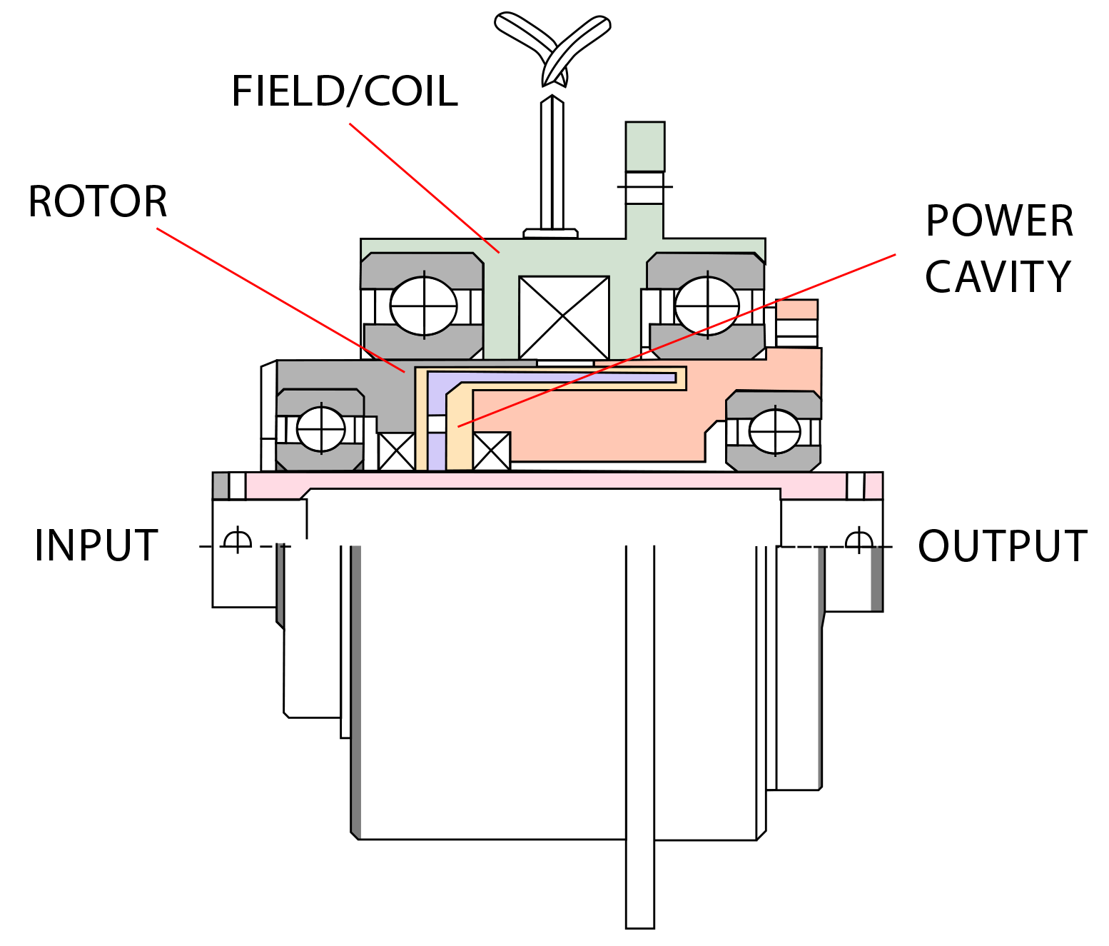
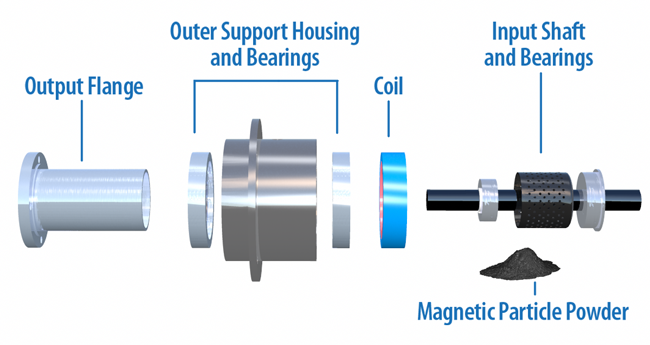
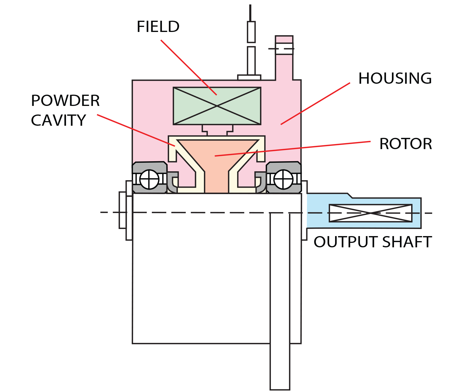
Engagement: Magnetic particles (very similar to iron filings) are located in the powder cavity. Without any voltage/current, they sit in the cavity; however, when voltage/current is applied to the coil, the magnetic flux that is created, tries to bind the particles together, almost like a magnetic particle slush. As the voltage/current is increased, the magnetic field builds, strengthening the bind of the particles. The clutch rotor passes through the bound particles, causing drag between the input and the output during rotation. Depending upon the output torque requirements, the output and the input may lock up, and torque transfer can be 100%.
Disengagement: When current/voltage is removed from the clutch, the input is free to turn with the shaft. Since magnetic particle powder is in the cavity, all magnetic particle units have some type of minimum drag associated with them.
Cycling: Cycling is achieved by turning the voltage/current to the coil on and off. Slippage should occur only during acceleration. When the clutch is running, there is no relative slip (if the clutch is sized properly), unless slippage is desired. Torque transfer is 100% efficient.
Electromagnetic Particle Brakes
Magnetic particle/current brakes are unique in their design from other electromagnetic brakes because of the wide operating torque range available. Like an electromagnetic brake, torque to voltage is almost linear; however, in a magnetic particle brake, torque can be controlled very accurately (within the operating rpm range of the unit). This makes these units ideally suited for tension control applications, such as wire winding, foil and film tension control and tape tension control. Because of their fast response, they can also be used in high cycle applications, such as magnetic card readers, sorting machines and labeling equipment.
Fast response and accurate control: Voltage to torque is almost linear, so engagement is extremely fast, and controllability of magnetic particle units is very accurate.
Stable torque: Torque is independent of speed, but is proportional to the voltage/current applied to the field, allowing stable torque throughout the units operating rpm range
Long life: Because the wear rate of magnetic particles is gradual instead of severe, the units have a very long life.
Excellent slip capacity: Because of the units' excellent heat dissipation, and because of their construction, they can operate in a constant slip mode (within max allowable wattage), which makes them ideal for tension controlling applications.
Engagement: Magnetic particles (very similar to iron filings) are located in the powder cavity. Without any voltage/current, they sit in the cavity; however, when voltage/current is applied to the coil, the magnetic flux that is created, tries to bind the particles together, almost like a magnetic particle slush. As the voltage/current is increased, the binding of the particles becomes stronger. The brake rotor passes through these bound particles. The output of the housing is rigidly attached to some portion of the machine. As the particles start to bind together, a resistant force is created on the rotor, slowing, and eventually stopping the output shaft.
Disengagement: When current voltage is removed from the brake, the input is free to turn with the shaft. Since magnetic particle powder is in the cavity, all magnetic particle units have some type of minimum drag associated with them.
Cycling: Cycling is achieved by turning the voltage/current to the coil on and off.
Hysteresis Permanent Magnet Clutch or Brake
Depending upon the mounting method, these units can function as either a clutch or a brake. Torque is generated magnetically, but is a function of the unit's mechanical setting. Each unit has an individual torque range. Once that torque is set, torque is generally stable, regardless of speed (within the unit's speed range). This makes these units ideally suited for tension control applications. Paper, film, foil, wire and other material tensions can be easily controlled. Since these units do not require a power supply, they are very cost effective. Typical applications include motor test stands, small wire winding, bottle cap machinery and labeling equipment. Since the units are sealed and do not develop wear particles, they are also adaptable to medical equipment and office automation machinery that requires control for paper tension. (Office automation versions of these units are extremely cost effective.)
No electrical power needed: The permanent magnet hysteresis units do not require any external power, which means their function is independent from power fluctuations.
No contamination: Since there are no wearing parts, and the units are sealed, there are no wear particles from these units that can contaminate your machine.
Stable torque: A consistent torque is maintained, regardless of allowable slip speed, due to the hysteresis principle.
Minimal stick slip: Since torque is transmitted magnetically, there is no friction from which to break away. This means that static and dynamic torques are almost the same.
Hysteresis Permanent Magnet Clutches or Brakes - How they work video
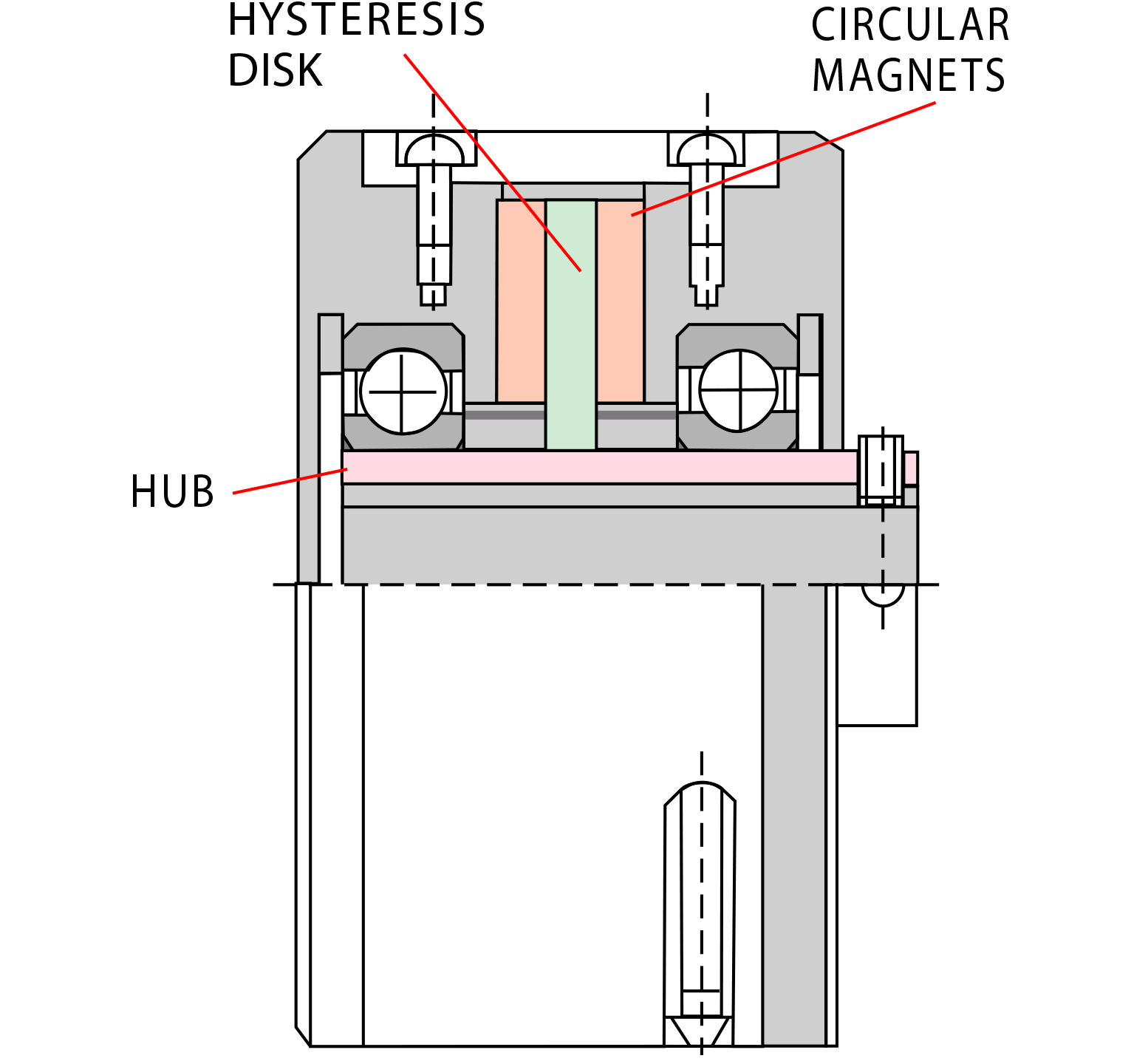
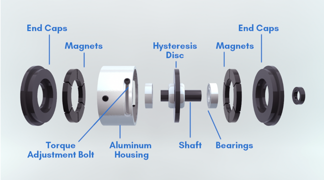
Function: Most units contain a hysteresis disk, which is directly attached to the hub that passes through the clutch/brake. Two circular multiple pole magnets are solidly attached internally within the unit. The magnets face each other with the hysteresis disk between them. There is an air gap between the magnets and the hysteresis disk, so the hysteresis disk can turn without any frictional contact. The opposing circular magnets set up magnetic flux, which causes drag on the hysteresis disk, which in turn, causes drag to the hollow hub in the unit.
To increase or decrease the amount of output drag, the units are manually adjustable. As the magnet poles are aligned north to north and south to south with each other, they produce the maximum amount of drag on the disk. As the poles are changed from a north to south alignment, the flux passes directly through the hysteresis material, reducing the amount of drag on the bore of shaft of the unit.
Powered Hysteresis Clutches
Electrical hysteresis units have an extremely wide torque range. Since these units can be controlled remotely, they are ideal for test stand applications where varying torque is required. Since drag torque is minimal, these units offer the widest available torque range of any of the hysteresis products. Most applications involving powered hysteresis units are in test stand requirements.
Fast response: Torque is independent of slip speed. It is also directly proportional to coil current, making response time extremely quick.
Repeatability: Under identical operating conditions, the unit will be able to duplicate it's performance. This makes it ideal for many testing applications.
Smooth operation: Since the unit transmits torque via magnetic flux, the torque is smooth throughout its operating rpm range.
Long life: Since torque is transmitted via an electromagnetic field, there are no wearing parts involved in the normal operation of the unit (except for bearings and seals). This means extremely long life. Hysteresis units will outlast any other type of electromechanical unit.
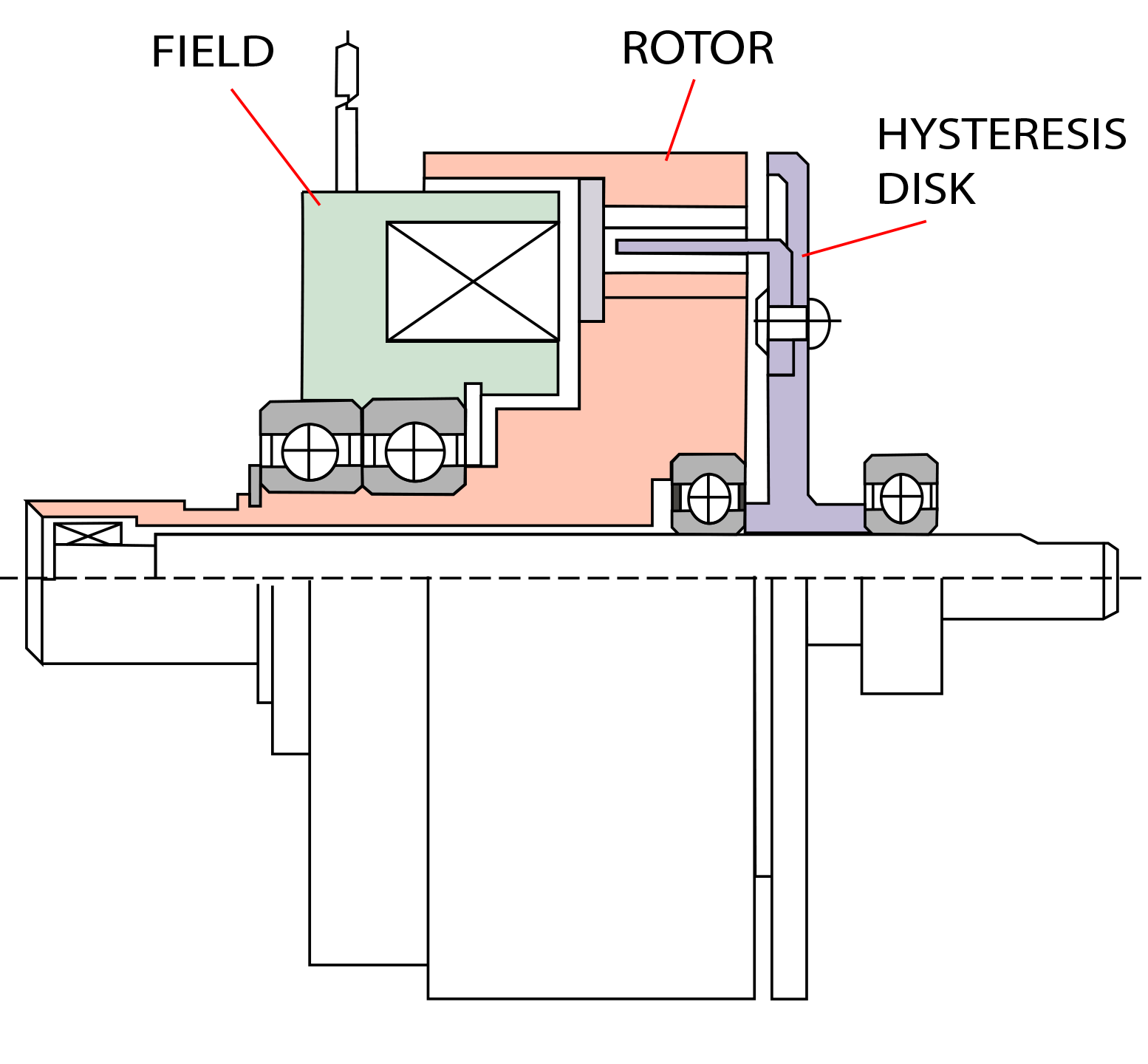
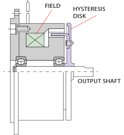
Engagement: When the current/voltage is applied to the field, it creates magnetic flux. This flux passes into the rotor portion of the field. The hysteresis disk physically passes through the rotor without touching. These disks have the ability to become magnetized depending upon the strength of the flux (this dissipates when flux is removed). This means, as the rotor rotates, magnetic drag between the rotor and the hysteresis disk take place causing rotation. In a sense, the hysteresis disk is pulled after the rotor. Depending upon the output torque required, this pull eventually can match the input speed giving a 100% lock up.
Disengagement: When current/voltage is removed from the clutch, the armature is free to turn, and no relative force is transmitted between either member; therefore, the only torque seen between the input and the output is bearing drag.
Cycling: Cycling is achieved by turning the voltage/current to the coil on and off. Slippage should occur only during acceleration. When the clutch is running, there is no relative slip (if the clutch is sized properly), unless slippage is desired. Torque transfer is 100% efficient.
Powered Hysteresis Brakes
Electrical hysteresis units have an extremely wide torque range. Since these units can be controlled remotely, they are ideal for test stand applications where varying torque is required. Since drag torque is minimal, these units offer the widest available torque range of any of the hysteresis products. Most applications involving powered hysteresis units are in test stand requirements.
Fast response: Torque is independent of slip speed. It is also directly proportional to coil current, making response time extremely quick.
Repeatability: Under identical operating conditions, the unit will be able to duplicate it's performance. This makes it ideal for many testing applications.
Smooth operation: Since the unit transmits torque via magnetic flux, the torque is smooth throughout its operating rpm range.
Long life: Since torque is transmitted via an electromagnetic field, there are no wearing parts involved in the normal operation of the unit (except for bearings and seals). This means extremely long life. Hysteresis units will outlast any other type of electromechanical unit.
Engagement: When current/voltage is applied to the field, it creates an internal magnetic flux. That flux is then transferred into a hysteresis disk passing through the field. The hysteresis disk is attached to the brake shaft. A magnetic drag on the hysteresis disk allows for a constant drag, or eventual stoppage of the output shaft.
Disengagement: When current/voltage is removed from the brake, the hysteresis disk is free to turn, and no relative force is transmitted between either member; therefore the only torque seen between the input and the output is bearing drag.
Cycling: Cycling is achieved by turning the voltage/current to the coil on and off.